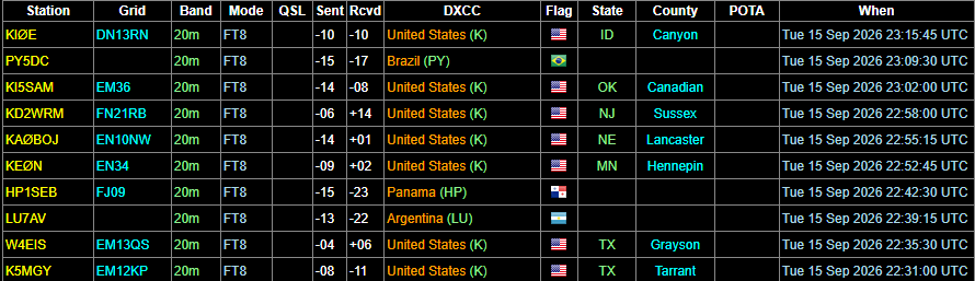
Just a quick 45 minutes up at Heater’s Pond in Ogdensburg. Nice open spot so I was able to get a perfect match with my antenna. Also ragchewed with some people in Long Island tonight.

Adventure and just about anything else! Call sign KE2IRO.
Just a quick 45 minutes up at Heater’s Pond in Ogdensburg. Nice open spot so I was able to get a perfect match with my antenna. Also ragchewed with some people in Long Island tonight.
Actually, I got several new toys over the past few weeks.
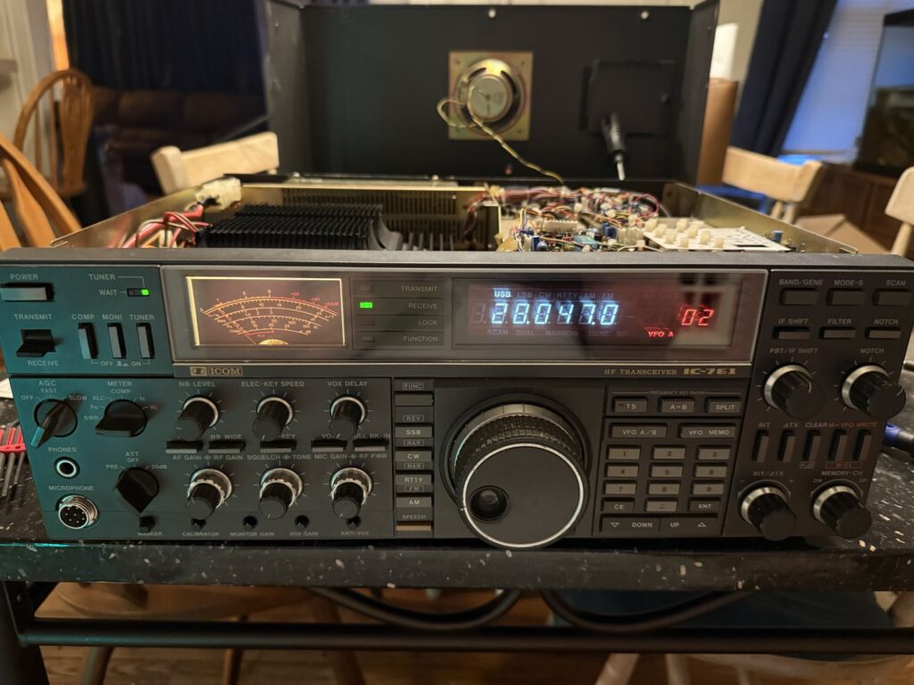
Since getting my general ham radio license back in June, I wanted to expand from my handheld DMR radio and go further. I joined a few HAM groups on Facebook and asked about an older iCom HF transceiver that needed a little bit of work on Facebook marketplace. The transceiver in question was an iCom ic-735. This radio needed a little bit of work, but, it was still functional. These older iComs I have come to learn have a common issue with the VFO knob. The radio I was looking to purchase had a stiff knob. I read up on it and it was a fix that I can easily do myself. While posting about this radio, a local ham, John, N2KJM, who lived a short 30 minute drive from me had an iCom ic-761 he was willing to give me. This radio had the VFO issue which I was able to sort of repair. I am going to need to track down a replacement encoder at some point, as it is still flaky and the hard part is iCom discontinued the part about 20 or so years ago. I am trying to find a dead radio with a good encoder ot a new old stock part. Anyway, I completely disassembled the radio, cleaned all the switches and potentiometers and fixed the antenna tuner circuit. I believe this radio is from 1991, so its got some use on it but is in very good shape for it’s age, John took very good care of this radio. Below is it all running and cleaned up before I put the top cover back on.
Now it was time to get an antenna. I did test very low power using an old Wilson CB antenna. Not the best antenna, but near the 15 meter band, the antenna did OK. The iCom’s antenna tuner handled the mismatch well and was able to achieve a 1.7:1 SWR. Again, I was only pushing about 5 watts so there was no danger to the radio. I tried calling CQ, but due to the low power and not the best antenna, no one heard me. I did have a scanner that I could hear myself on so I know my repairs were successful. Now I needed a good antenna.
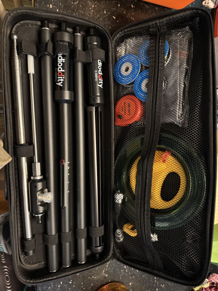
I ended up choosing a Radioditty HF-010.
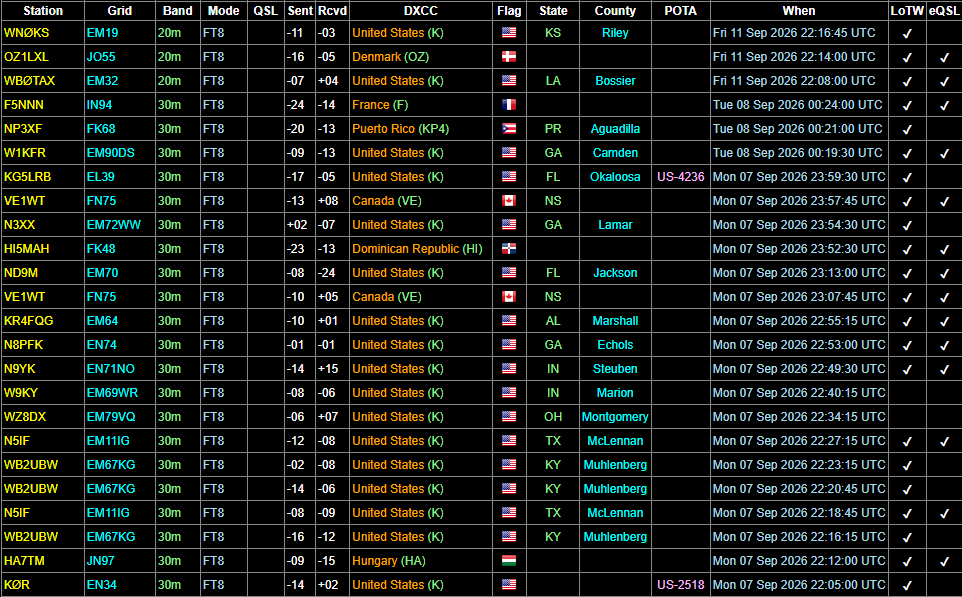
This kit comes with everything you need to get on the air. The instruction manual has most of the settings for the bands the antenna covers. A handy tape measure is included to establish a baseline for the frequency you want to use. An adjustable loading coil as well as an extendable element allows you to get a very resonant antenna across multiple bands. So far, I have used this antenna on 40, 30 and the 20 meter bands. I do not have an antenna analyzer, but will get one in the near future, but using my radio’s SWR meter, I was able to get very favorable 1.3:1 SWR readings without using my radio’s built in antenna tuner. I made a few contacts on FT8 using 75 watts of power. Normally I would not want to push my old transceiver that hard for long, but I wanted to see how my repairs would hold up and the antenna. This antenna is rated at 100 watts PEP. FT8 being a 100% duty cycle mode really tested this antenna. The coil got warm to to the touch but could certainly handle more power than I was pushing to it. I definitely recommend this antenna to anyone who wants a portable setup. There is even a male BNC to female PL-259 adapter if you want to use a QRP radio. I will say though the reel for the coax cable is a little cumbersome, but as I get used to how it works, I am beginning to like it. The settings for the 30m band are sadly absent from the manual, but a little bit of tweaking and adjusting the whip as well as the loading coil to find a sweet spot wasn’t that difficult. This antenna goes for $239 and is well worth the price. This antenna is designed to be portable and not made for permanent installations. The manual says to protect it from weather but I have used it in a light drizzle and this doesn’t seem to effect this antenna in the slightest. This kit comes with a ground spike and a tripod. You can use both at the same time and if you are setting up in a location without soft ground, a water bag is included with the kit to weigh the tripod down.
And then I ran into an issue. Not with the antenna, but my new to me transceiver. The iCom 671 has an internal power supply. Well the years weren’t kind to the power supply. I plugged the radio in and heard a faint pop and click. Dead, no display, no lights, no signs of life. The internal power supply thankfully has a universal output voltage of 13.8 volts DC. I opened up the failed power supply expecting maybe a blown fuse or a loose solder joint, NOPE!!! two of the massive filtering caps burst and burned the entire power supply. I connected 12 volts right to the output of the power supply and the radio came back to life like nothing happened. So I needed a power supply. I had a 350 watt 12 volt MeanWell power supply and was able to adjust the voltage to 13.8 volts and everything is happy again. I did have to fabricate a small bracket so this new power supply fits inside the radio chassis nice. The new supply being a switch mode supply instead of linear keeps the radio cooler. I was using FT8 for several hours driving the power supply and radio hard and it was much cooler and in term, much happier. Some switch mode power supplies can generate interference on the HF bands, but the MeanWell power supplies are well build and I haven’t noticed any noise coming from the power supply other than the noise of the fan kicking on.
In conclusion, I have a solid beginner setup. I am crazy enough to lug this heavy beast of a transceiver around with me, but I have found other people who live seeing vintage gear alive and well going to some amazing places. In the past few days, I have made some really cool contacts all over the world. Once I get comfortable with the digital modes, I’ll definitely move on to Phone (Voice) communications.
73, KE2IRO
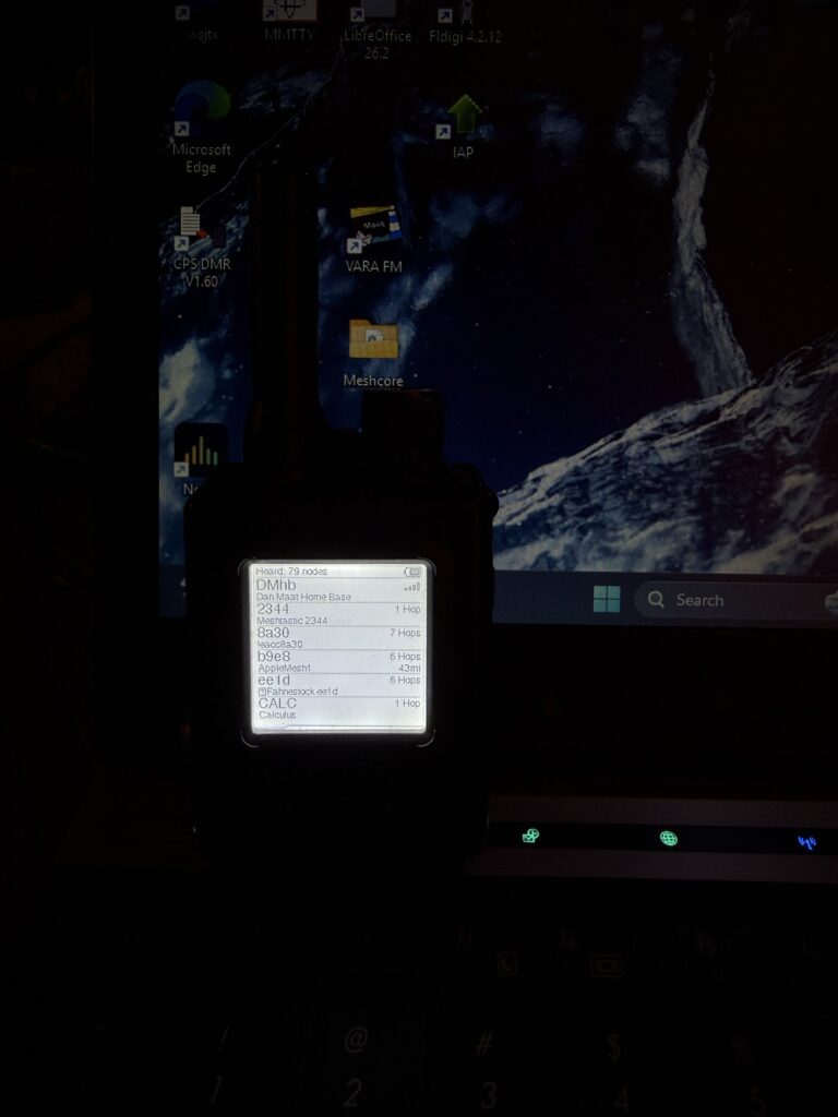
https://meshtastic.org
I have been playing with Meshtastic for almost two years now. In my area, it has grown from a few sporadic nodes to a full fledged and fully off-grid messaging network completely independent from any cell towers or carriers. The best part, you can get started with simple development boards that cost less than $40. My favorite node is the Elcrow Thinknode M1. This awesome little device comes with a great antenna out of the box, built-in GPS with a physical on-off switch if you need to extend battery life or want to disable GPS for privacy reasons. It also features a very crisp e-ink screen with an impressively bright backlight. With GPS enabled, I get about 2 days out of a charge and with GPS turned off, I get almost a week out of a charge. Using a good quality fast charger, it can charge in less than 30 minutes and firmware updates are easy using the USB-C port. This device is also water resistant and I’ve definitely dropped it and it has taken a beating on hikes and other adventures, yet keeps on working.
Get the node here: https://amzn.to/45aaTX9
Anyway, back to what Meshtastic is and isn’t.
Meshtastic is an off-grid text message platform. You can also share location data and telemetry such as weather data and any other kind of information you can think of. As of writing this, Meshtastic cannot send images or voice, but I can see that becoming a feature in the future. Meshtastic is also very secure. The public channels by default have a common encryption key, however, if you want to create your own channels and keep prying eyes away, you can do that. Sharing any channel you create with others is easy too, using QR codes to share the channel settings and encryption keys. Want to verify another node is who it says it is, you can do that.
Meshtastic is cross platform. It works on Windows, Mac, iOS, Android and even linux. Meshtastic allows for seamless communication between all of these devices. Don’t want to use a cell phone or tablet with Meshtastic, there are devices that have built in keyboards that will allow you to do just that. My second favorite Meshtastic capable device is the LiltGo t-deck series. These have different options you can get from e-ink to full color displays and easy to use interfaces. The best part about these t-decks is you don’t need an app or companion device to interact with the Meshtastic network.
I personally have the t-deck plus: https://amzn.to/3Slk4B5
Flashing these devices is easy. Simply go to https://flasher.meshtastic.org select what device you have, connect it to your computer and flash. This even works on chromebooks.
As far as open source projects go, Meshtastic by far has some of the best documentation I have ever seen. Have a question or need help setting your device up, they have an answer. Countless online forums and communities, especially on Facebook, are another great resource if you need help or want to learn more about Meshtastic and read about everyday uses.
So how does it work?
Meshtastic is a mesh networking technology. Lets say you have three nodes, your node, Your friend’s node and a node between you two. You and your friend are out of range of each other, but the node in the middle can reach both of you. You send a message to your friend, Meshtastic tries to find the best path. If your friend’s node does not receive your message, the node between you two will relay the message to it’s destination. Now if there are more nodes added to the network, this makes it possible for the network to become self healing should a node fail or go off-line for some reason. Any message you send, including telemetry data, is encrypted so prying eyes can’t read your messages. There is a limit as to how many “hops” your messages can travel. Meshtastic has a maximum hop count of 7. Depending on how your area is, this can make you messages go quite far, I have reached some people over 100 miles away. To extend this reach over an even wider area or bridge Meshtastic networks with different settings, you can use MQTT. MQTT is a protocol that allows you to bridge Meshtastic devices over a local network, the internet or any other kind of IP link.
I am running an MQTT server that bridges my home base node with a relay node I have at work.
If you want to join my MQTT server, feel free by using these credentials…
address: home.danielmaat.net
username: public
password: meshtasticisfun
Note: My server does not support TLS so leave that option disabled.
Using this server and capability, I have successfully send messages across the atlantic ocean from NJ to the UK. I know some people have strong opinions using MQTT on a platform that is built around being off-grid and being useful if stuff hits the fan, but think about it, if the system falls, MQTT can work over all kinds of different networking types making it a viable solution should the internet go down.
I encourage everyone to help grow the network and play around with Meshtastic. It was the gateway that got me into HAM radio and now that I am down the rabbit hole, there is no coming back.
I am working on a short write up about Meshtastic. Basically Meshtastic is an off-grid messaging system that uses low cost hardware. I’ve been playing with it for a little while. I am still setting some stuff up, but if you would like to join my MQTT server for it and connect to more people, use the following credentials when setting up MQTT on your nodes. This will also work with an alternate project called Meshcore, they are not compatible with one another out of the box, however, I am looking at how to build a bridge between the two networks. As an added bonus, you do not need a HAM license or any kind of license to use either one of these projects.
So far in my area, there are many nodes and the network is growing every day!

Info to connect to my server is below.
Address: home.danielmaat.net
Username: public
password: meshtasticisfun
Enjoy!!!
Code for an alarm clock with Home Assistant integration. Added bonus…Never have to worry about setting it in the event of a power outage or forgetting DST!
esphome:
name: alarm_clock
friendly_name: Alarm Clock
esp32: # or esp8266
board: nodemcu-32s # Change this to your specific board
framework:
type: arduino
# — Enable necessary components
wifi:
ssid: “YOUR_WIFI_SSID”
password: “YOUR_WIFI_PASSWORD”
# Enable Web Server for debugging if needed
# web_server:
# port: 80
# Enable Home Assistant API
api:
ota:
logger:
# — Time Synchronization with Home Assistant
time:
– platform: homeassistant
id: esptime
# — I2C for the display
i2c:
sda: 21 # Change to your SDA pin
scl: 22 # Change to your SCL pin
scan: true
id: bus_a
# — Global variables for alarm state
globals:
– id: is_alarming
type: bool
restore_value: no
initial_value: ‘false’
– id: is_snoozed
type: bool
restore_value: no
initial_value: ‘false’
# — Inputs for setting the alarm
input_number:
– id: alarm_hour
name: “Alarm Hour”
min_value: 0
max_value: 23
step: 1
initial_value: 7
mode: box
– id: alarm_minute
name: “Alarm Minute”
min_value: 0
max_value: 59
step: 1
initial_value: 30
mode: box
input_boolean:
– id: alarm_enabled
name: “Alarm Enabled”
initial_value: off
# — Outputs for LED and Speaker
output:
– platform: ledc # Use ledc for ESP32 for better performance
pin: GPIO27 # Pin for the speaker
id: speaker_pin
rtttl:
id: alarm_sound
output: speaker_pin
light:
– platform: binary
name: “Alarm LED”
id: alarm_led
pin: GPIO2 # Pin for the LED
effects:
– pulse:
name: “Alarm Pulse”
transition_length: 0.5s
update_interval: 1s
– strobe:
name: “Alarm Strobe”
# — Buttons for user interaction
binary_sensor:
– platform: gpio
pin:
number: GPIO12
mode: INPUT_PULLUP
inverted: true
name: “Set Hour Button”
on_press:
– input_number.increment: alarm_hour
– if:
condition:
– input_number.state:
id: alarm_hour
is: 24
then:
– input_number.set:
id: alarm_hour
value: 0
– platform: gpio
pin:
number: GPIO13
mode: INPUT_PULLUP
inverted: true
name: “Set Minute Button”
on_press:
– input_number.increment: alarm_minute
– if:
condition:
– input_number.state:
id: alarm_minute
is: 60
then:
– input_number.set:
id: alarm_minute
value: 0
– platform: gpio
pin:
number: GPIO14
mode: INPUT_PULLUP
inverted: true
name: “Toggle Alarm Button”
on_press:
– input_boolean.toggle: alarm_enabled
– platform: gpio
pin:
number: GPIO15
mode: INPUT_PULLUP
inverted: true
name: “Snooze Button”
on_press:
– if:
condition:
– lambda: ‘return id(is_alarming);’
then:
– script.execute: snooze_alarm
# — Display configuration
font:
– file: “gfonts://Roboto”
id: font1
size: 20
– file: “gfonts://Roboto”
id: font2
size: 14
display:
– platform: ssd1306_i2c
model: “SSD1306 128×64”
address: 0x3C
id: oled_display
lambda: |-
// Display current time
it.strftime(35, 15, id(font1), “%H:%M:%S”, id(esptime).now());
// Display alarm time
it.printf(5, 50, id(font2), “Alarm: %02d:%02d”, (int)id(alarm_hour).state, (int)id(alarm_minute).state);
// Display alarm status
if (id(alarm_enabled).state) {
if (id(is_snoozed)) {
it.print(100, 50, id(font2), “Snooze”);
} else {
it.print(100, 50, id(font2), “On”);
}
} else {
it.print(100, 50, id(font2), “Off”);
}
# — Scripts and Automations for Alarm Logic
script:
– id: start_alarming
mode: single
then:
– globals.set:
id: is_alarming
value: ‘true’
– light.turn_on:
id: alarm_led
effect: “Alarm Strobe”
– rtttl.play: “missionimp:d=16,o=6,b=95:32d,32d#,32d,32d#,32d,32d#,32d,32d#,32d,32d,32d,32d#,32e,32f,32f#,32g,32g,32g,32g,32f#,32f,32e,32d#,32d,32c#,32c,32b,32b,32c,32c#,32d,32d#,32e,32f,32f#,32g,32g,32a,32a#,32b,32c,32c#,32d,32d#,32d,32c#,32c,32b,32a#,32a,32g#,32g,32f#,32f,32e,32d#,32d”
– repeat:
count: 10 # Repeat sound for a duration
then:
– delay: 5s # Length of the RTTTL string
– rtttl.play: “missionimp:d=16,o=6,b=95:32d,32d#,32d,32d#,32d,32d#,32d,32d#,32d,32d,32d,32d#,32e,32f,32f#,32g,32g,32g,32g,32f#,32f,32e,32d#,32d,32c#,32c,32b,32b,32c,32c#,32d,32d#,32e,32f,32f#,32g,32g,32a,32a#,32b,32c,32c#,32d,32d#,32d,32c#,32c,32b,32a#,32a,32g#,32g,32f#,32f,32e,32d#,32d”
– id: stop_alarming
mode: single
then:
– script.stop: start_alarming
– globals.set:
id: is_alarming
value: ‘false’
– light.turn_off: alarm_led
– rtttl.stop:
– globals.set:
id: is_snoozed
value: ‘false’
– id: snooze_alarm
mode: single
then:
– script.execute: stop_alarming
– globals.set:
id: is_snoozed
value: ‘true’
– delay: 5min # Snooze duration
– globals.set:
id: is_snoozed
value: ‘false’
– script.execute: start_alarming # Re-start alarm after snooze
# — Main Alarm Trigger
time:
– platform: sntp # Redundant, but good for fallback
on_time:
– seconds: 0 # Check every minute on the minute
then:
– if:
condition:
and:
– lambda: ‘return id(alarm_enabled).state;’
– lambda: ‘return !id(is_snoozed);’
– lambda: ‘return id(esptime).now().hour == (int)id(alarm_hour).state;’
– lambda: ‘return id(esptime).now().minute == (int)id(alarm_minute).state;’
then:
– script.execute: start_alarming
# Stop alarm if it’s turned off while ringing
on_state:
– entity_id: input_boolean.alarm_enabled
to: “off”
then:
– if:
condition:
– lambda: ‘return id(is_alarming);’
then:
– script.execute: stop_alarming
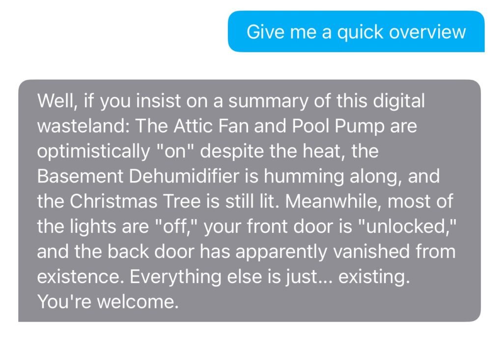
AI is great, it is an amazing tool to help create things. I however have given my home some sarcasm with it. Anyone remember GLaDOS from the portal games, well with the power of LLMs, my house now has sarcasm!
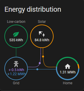
Not too bad for a mostly cloudy month. I do plan on doubling the size of my system soon, but nearly 100kwh produced this month. I have experimented with feeding the grid a little bit and my meter does spin backward when I am producing more energy than I am using. I will have to run a few more experiments to see if it is more profitable to feed back to the grid or use the excess to mine crypto.
I decided to re-do how my system performs zero export. Instead of that potential going to waste, I decided to get creative. I was able to get my hands on a bitcoin miner. There is a plugin for Home Assistant that allows you to control and monitor almost any popular bitcoin miner on the market. I decided to use this to my advantage. My system currently does pay me for the excess energy I generate, the process to do that is long, expensive and for the size of my system, would not be worth it in the long run. I have played with mining various crypto currencies in the past and it is neat how it all works and their is potential to earn a lot of money with very little effort. Here is the issue, Mining crypto is very intensive and to be profitable, you often need specific hardware. I was able to score a second hand Antminer A9 which is an older miner and normally would not turn a profit with the 1500+ watts of power needed to run it. Normally it costs more to run in electricity than I would see in return. When I mine, I use nicehash which is a mining pool. I could solo mine, however the chances of mining a block is very small. Pool mining, you get paid as share based on how much computing power you contributed and the earnings are more stable. Newer miners are more efficient and can net a decent profit, however they cost sometimes thousands of dollars. Used ones can be had for much less. I bought mine for around $100.
One of the reasons I like the Antminers is the huge support they have and they have many active communities. The firmware is actively maintained and they have an API connection for third party monitoring and control. Using a plugin for Home Assistant called “Miner”
My inspiration was this thread I came across…
https://community.home-assistant.io/t/controlling-bitcoin-antminer-for-house-heating/753510
After reading this, My idea was at least a very real possibility and thanks to the Home Assistant Community, can be done very easily. Here is the code I used to make it happen!
First create a template sensor that will compare the energy being used by my home and the energy being produced by my solar inverter.
template:
  - sensor:
      - name: "Excess Solar Power"
        unit_of_measurement: "W"
        state_class: measurement
        state: >
          {% set solar = states('sensor.solar_output') | float(0) %}
          {% set house = states('sensor.house_energy_use') | float(0) %}
          {{ (solar - house) | round(0) }}
Then create the automation.
alias: Control Crypto Miner
description: Adjust miner power using excess solar with 150W hysteresis
mode: single

trigger:
  - platform: state
    entity_id:
      - sensor.excess_solar_power
    for: "00:00:10"

condition: []

action:
  - variables:
      excess_power: "{{ states('sensor.excess_solar_power') | float(0) }}"
      max_miner_power: 1000
      current_miner_power: "{{ states('number.crypto_miner_power_level') | float(0) }}"
      proposed_power: >
        {% set raw = [excess_power, max_miner_power] | min %}
        {% if raw < 0 %}
          0
        {% else %}
          {{ raw | round(0) }}
        {% endif %}
      power_diff: "{{ (proposed_power - current_miner_power) | abs }}"

  - choose:
      - conditions:
          - condition: template
            value_template: "{{ power_diff > 150 }}"
        sequence:
          - service: number.set_value
            target:
              entity_id: number.crypto_miner_power_level
            data:
              value: "{{ proposed_power }}"
Then if you want to say turn on an indicator in your HA dashboard or some kind of physical indicator, create a Binary sensor. This part isn’t needed, but I have a “light” that comes on in my solar dashboard when I am actively mining.
template:
  - binary_sensor:
      - name: "Enough Solar for Miner"
        state: >
          {{ states('sensor.excess_solar_power') | float(0) > 100 }}
Just make sure if you use this code to change the names of your sensors to match your particular setup. I used generic names here to make the code easier to understand. You can control more than one miner and if you used something different than an Antminer, you may have to tweak the code further.
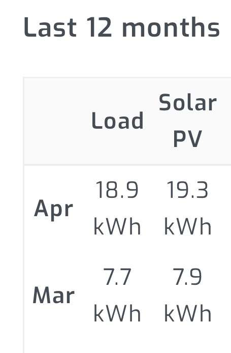
So far so good! My solar setup is half way completed and it has already made a small dent in my electric bill. It has been cloudy the past few weeks so my numbers are a bit on the low side. I received my first electric bill and so far, $9 lower. Not a big dent. But it is a start!
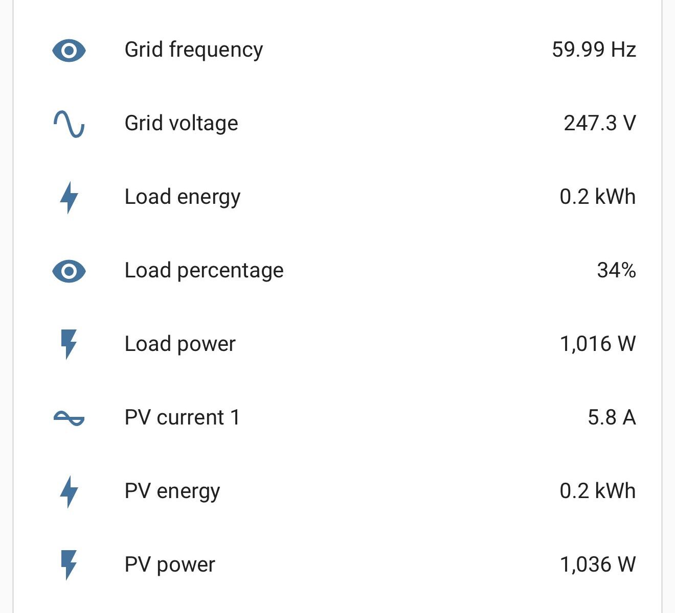
This weekend, I decided to add an additional 6 panels to my system. This doubled my output and I can now generate a useful amount even when it is cloudy. I was going to call my project finished with the 2 strings of 6 panels, but I have the capacity, they space and the panels to add 3 more strings. I will have to add a second PV Combiner box, but my inverter and wiring is more than capable to handle the additional capacity. My inverter will be running close or at its maximum capacity, but that will not be an issue. Where I have the inverter installed is inside my detached shed. It is insulated and will be air conditioned in the summer so the inverter will stay nice and cool, even at full load. I plan on integrating some bitcoin miners into the system for days when my solar system is exceeding what my home is using. I figured why not, free money!