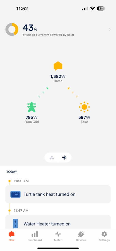
So a little bit out of order today because the weather has been so nice recently, but I have installed about 1/4 of my panels. After experimenting with different configurations, it turns out my inverter likes DC voltages above 180 vols, I have decided to configure my system with 4 strings of 6 panels. 6 panels in series and 4 strings in parallel. Today was a cloudy day and I wired up the first string and the 240 volt line to the inverter. The results so far are good. My Zero Export configuration is working and for a short time today I was able to 100% power my home with solar! I had a peak output of 780 watts.
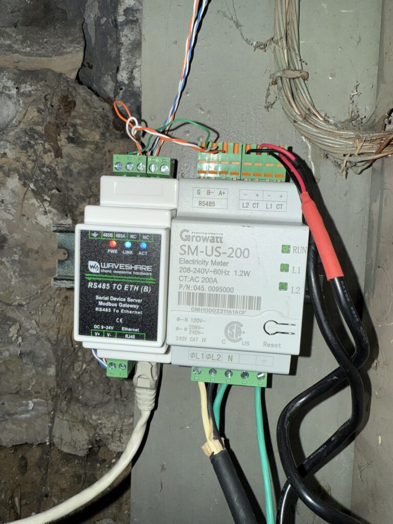
In order to not get a nasty gram from my power company, I needed to set up zero export. Basically what this does is prevent my solar system from feeding the grid. I thought about doing this and getting paid for my surplus production, but this process is more trouble than it is worth for me. In order to set up the zero export, my inverter needs to know how much power is flowing into and out of both my solar system and the power grid. These two little boxes do that. The bigger of the two boxes is the smart meter. This talks to the inverter and tells it how much power is flowing on the 2 main legs going into my house after my power meter. The issue I was having was the distance. MODBUS-RTU is a bus protocol for automation controls and other devices. It is also known as RS485. This really neat communication protocol uses two wires and is almost always universal between different manufacturers. It has become a standard in the solar industry because of its ease of use and easy to implement. My issue was my inverter is a good distance from my main panel. My solution was to send the data over my network. I am using MODBUS over tcp/ip which eliminates any distance limitations. In theory, I could extend the bus across the world and it wouldn’t matter. I have a second box in my shed with a WiFi bridge and it works flawlessly. I will soon set up a low voltage system in my shed to power this equipment as well as an additional raspberry pi running Solar Assistant for additional more detailed data. This raspberry pi will use the MODBUS protocol to communicate with the inverter and the smart meter and will relay that data to Home Assistant where I can get more advanced with some of my automations and create more detailed custom dashboards. The RS485 bridges I used are from WaveShare and the WiFi bridge I am using is a Vonets Val-11g-300
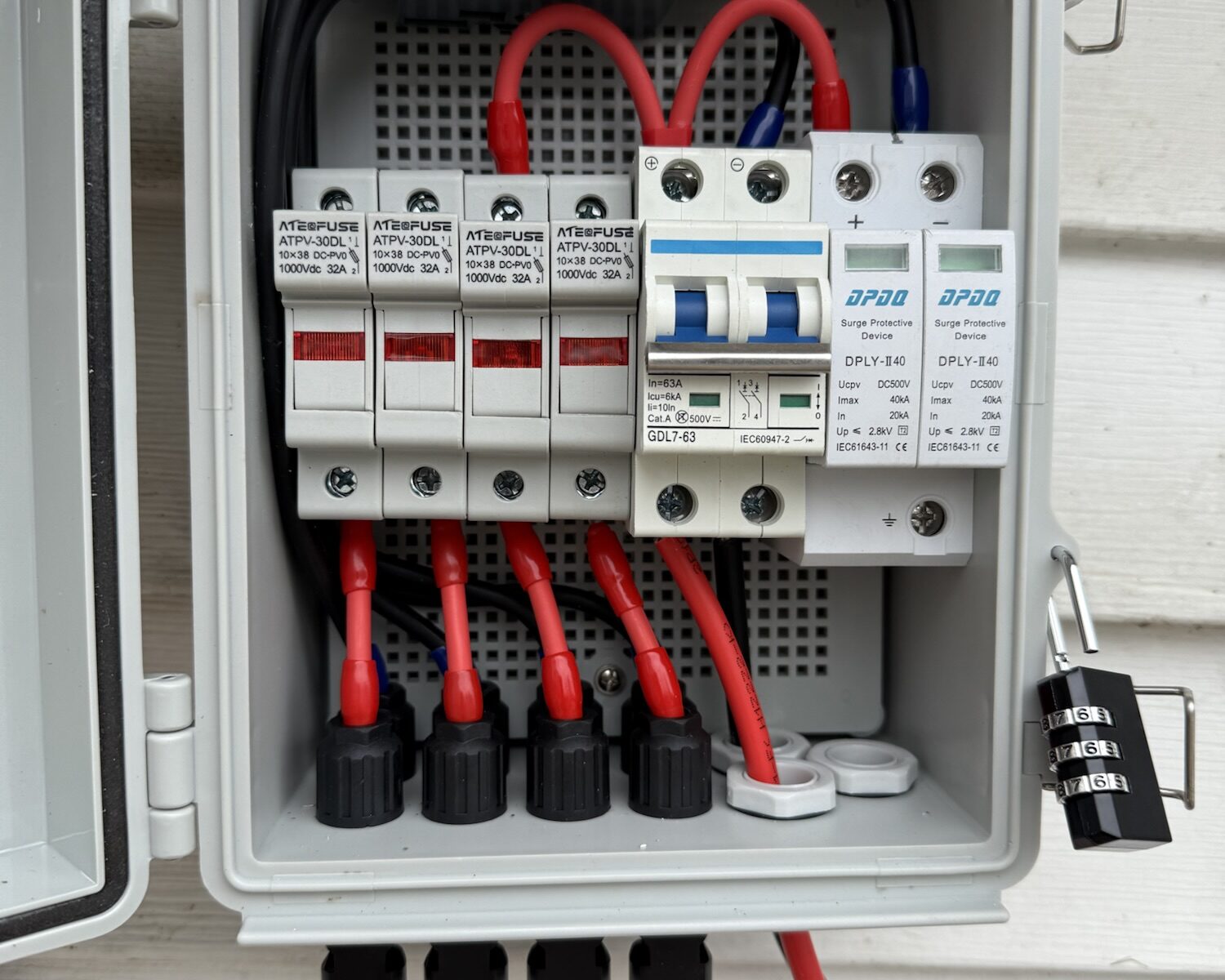
Today I decided to take advantage of the near 70 degree weather and started wiring up my solar system. I am still waiting on the inverter to come, but I have run the 240 line to the shed where the solar will be installed and have wired up the combiner panel and the DC shutdown switch. I went a little overboard on the wiring, I am using 10/3 for the 240 volt wiring which is rated at 30 amps. My system most likely will not push anything more than 15 amps but I decided to go this route so I can upgrade my system down the road if need be. The oversize circuit will have an added benefit of minimizing the voltage drop across the 75 feet of electrical wiring between the solar inverter and my main electrical panel. As for the DC side, I am using outdoor rated and UV resistant 10 gauge wiring. The wiring also has thick insulation designed to handle high voltage DC. The DC circuit for my panels will be running around 180 to 230 volts. Each string has the potential to operate at 6 amps and I plan to have 3 or 4 strings. The combiner panel has several safeguards. Each string is on an independent 15 amp fuse. The entire combiner box is protected by a 60 amp breaker and has surge and lightning protection modules protecting both the Positive and Negative connections for the system. Any fault current will be safely sent to ground protecting not only the system, but anyone near it. This will also prevent a fire if there is a voltage leak or fault wire.
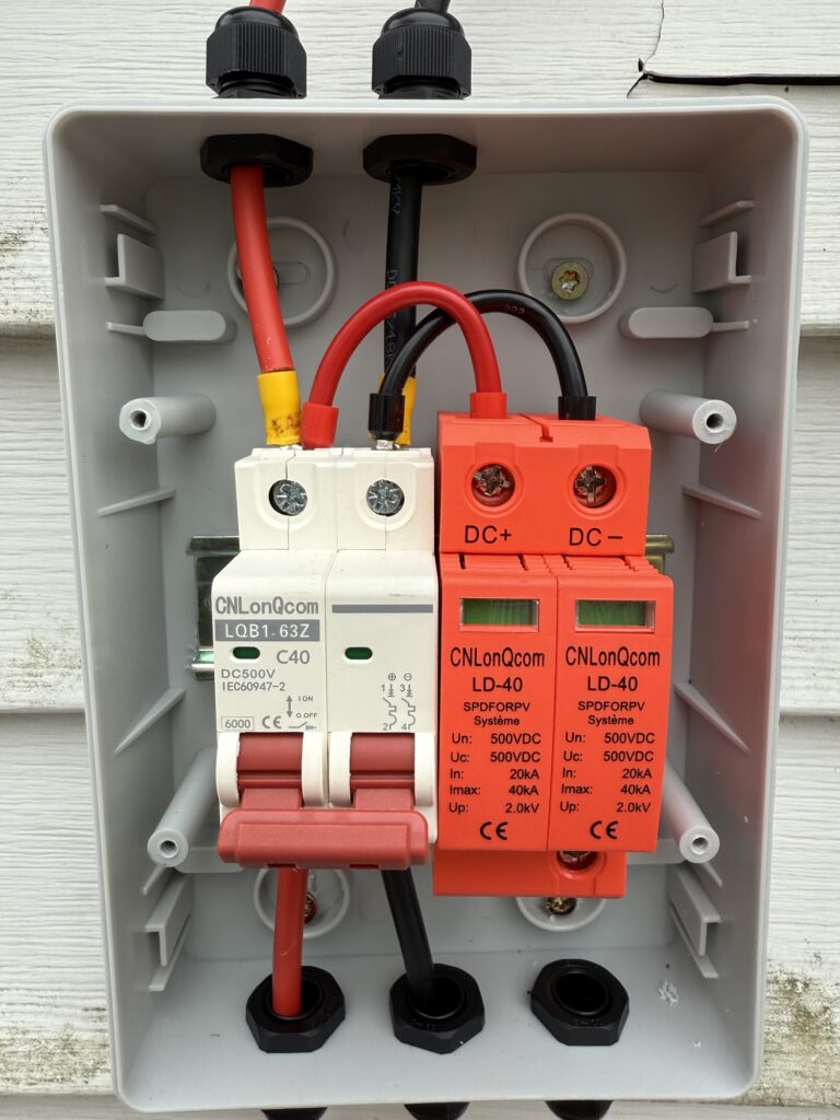
As an additional layer of protection, my DC shutoff switch is over rated and has additional surge suppression devices. The reason for the rapid DC shutdown is to kill power to the system if their is an emergency. The inverter is designed to shutdown in the event of AC power loss as a safety measure to protect linemen from getting electrocuted while working on power lines. The inverter will also shutdown in the event of DC power loss. My system will have both AC and DC shutdown switched located on the exterior of my shed so the solar system can be completely disconnected and safely shut down.
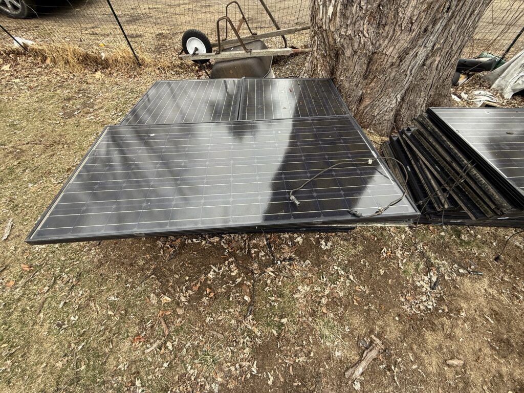
So due to the rising costs of electricity in my area, I have decided to dive in to solar energy. I am learning as I go and I want to share what I am doing and am open to any suggestions. So far I was able to purchase 30 used solar panels for next to nothing. Only 3 in the lot are broken, but amazingly still produce a good amount of power. Not only do I plan on supplementing my home’s power with solar, I want to move my home network equipment and servers on their own dedicated solar system to further reduce my energy usage. I am still gathering the necessary components to make everything work and to ensure it is all done safely. So far, I have the panels and soon the connectors, combiner box and inverter. I am also installing a rapid DC shutdown switch in case of emergencies. I will share here my progress and what I learn and improve upon as time goes on.
Welcome to my new site! I am working on posting content soon. So far all I have is how I set this site up and instructions on how to do it yourself. This site will contain a little bit of everything from outdoor adventures to electronics and more!